This was a collaborative graduate school class project for Tangible Interface Design.
The creative problem to solve was to create an environmental experience utilizing electronic components and an Arduino micro controller. My team was comprised of three students. We designed an interactive scarf that represented different seasons and weather. Since we only had 3 people, we each chose a section of the scarf to develop: Winter, Summer and Spring. I worked specifically on in the Spring module, but also programmed the music component on the Summer module and I also developed the way to stitch the sections together to present our project.


TANGIBLE COMPONENTS
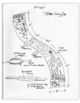
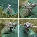
Fire Flies

The fire flies were created with yellow LEDs, jewelry components and fimo clay. After the clay was formed, the jewel components pressed into the clay, they were baked, cooled and then soldered to the wiring. The Arduino was programmed to randomly light them when the ambient lights dimmed.
Yellow Rose
A rose made from fimo was created with a light sensor embedded in it, then wired to the Arduino and connected to the random lighting fire flies.
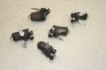
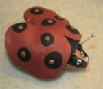
Cyber Bug

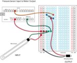
The cyber bug was created out of jewelry notions and a small pager motor wired to the pressure sensor. The bug was attached to the felt leaf. When the leaf was pressed at the base, the pager motor would vibrate and buzz the bug.
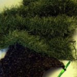
Leaf
The leaf was made from two colors of green felt sewn together with a channel that the sensor slipped into and where the bug was attached at the peak of the leaf.
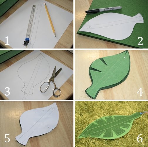
Making the Leaf
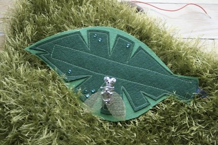
Final Leaf Assembly
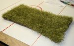
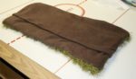
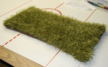
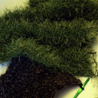
Patch of Grass (Duvet Cover)
My patch of grass was created by crocheting a rectangular piece and attaching this to a soft brown material backing with a pocket opening to insert all the electronic wiring and components. It was similar to a pillow case, or duvet cover to house the Arduino, the breadboards, battery and all the wiring. The crocheted section worked really well to feed the wires out of the way into the casing.
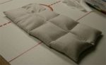
I originally created a buckwheat insert — but it was too bulky and heavy for my duvet — so I eliminated this. You can see this insert above.

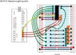
Components | Breadboards | Schematics
Developing electronic circuits was a new experience for me and being a visual person, I decided to create my own way to document how to make the various circuits that I used in my scarf. Here are two of the circuits that I developed and documented.
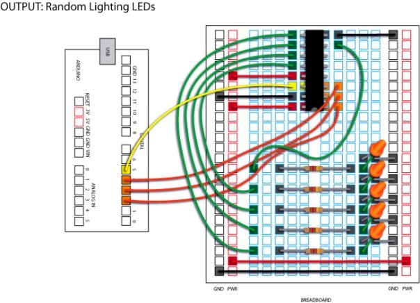

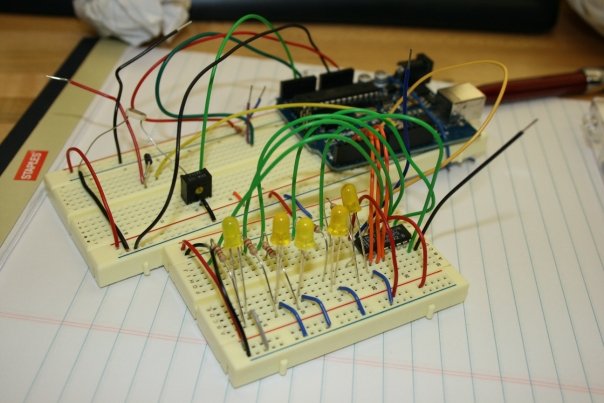
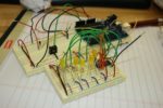
This is what the wiring looks like in reality! The green board is an Arduino micro controller which ties into a computer. You use a software program to create instructions for your interactive stuff then download it into the Arduino board (it has a little brain that tells the circuits what to do).
The two cream boards are called “bread boards.” These babies help you wire stuff up and test it before you actually solder everything together! Cool huh?
The above pictures my final breadboards. The Arduino sits at the back right of the long rectangular breadboard and has a USB port to attach to the computer to program. When the scarf is mobile, the circuits and Arduino run via a 9V battery assembly. The breadboard in the foreground is the circuit for the fireflies. The yellow LEDs in the board were used for the fireflies and were hard wired into the board with additional wire after the flies were created.
NOTE: Our final scarf was entered into a Regional Rochester Art Exhibition and won an award.